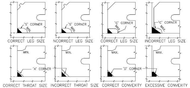
The finished welds shall be visually inspected and shall conform to the size and contour
specified in the drawings (Acceptable and defective weld profiles are illustrated in
Fig. 24 to 28). Conformity of fillet welds as to size and contour shall be determined by
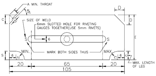
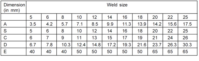
the use of gauges (See Appendix ‘B’) Concavity and excessive convexity of fillet welds
shall be marked for correction.
Welding gauges are essential tools in the welding industry for measuring, inspecting, and evaluating
welds. Made of metal or plastic and available in various shapes and sizes, they ensure welds meet
required standards for strength and durability. These gauges help maintain weld quality by providing
feedback on weld profiles, joint fit-up, dimensions, and welding parameters, allowing for the
identification and correction of defects.
Fillet Weld Gauges are tools used to measure the size of fillet welds, which are commonly found in
lap joints, T-joints, and corner joints. These gauges usually feature a set of blades or notches in
various sizes and are used for measuring various weld parameters.