CARBONATION TEST
1. Objective
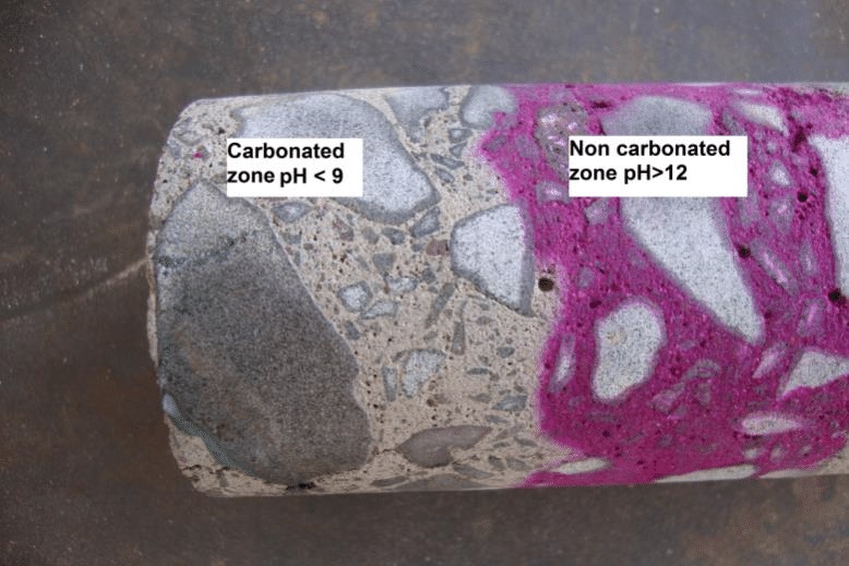
Carbonation is a process in which carbon dioxide from the atmosphere diffuses through the porous cover concrete and may reduce the pH to 8 or 9, at which the passivating/oxide film is no longer stable. Carbonation process involves the following two stages: First, the atmospheric carbon dioxide (CO2) reacts with water in the concrete pores to form carbonic acid (H2CO3). This is followed by reaction of the carbonic acid with calcium hydroxide [Ca(OH)2] to form calcium carbonate (CaCO3). This process leads to cause a reduction in the pH value of the pore solution from 12.5 to 13.5 to around 8 to 9, which causes depassivation of protective layer of the reinforcement bars and initiates their corrosion.
2. Application
Carbonation of concrete is one of the main reasons for corrosion of reinforcement. Oxygen and moisture are the other components required for corrosion of embedded steel. In this test, the depth of carbonation is determined. The rate of carbonation depends on the grade of concrete, permeability of concrete, whether the concrete is protected or not, depth of cover, time, etc.
3. Factors Influencing the Rate of Carbonation of Concrete
a) Amount of CO2 in air;
b) Relative humidity of concrete;
c) Amount of precipitation of CaCO3; and
d) Concrete carbonation resistance (concrete permeability and amount of Ca(OH)2 in concrete).
|
Fig. 1 : Carbonation Test on Concrete |
4. Reference
IS-516(Part 5/Sec 3):2021 “Part 5 Non-Destructive Testing of Concrete- Section 3 Carbonation Depth Test"
5. Procedure for Measurement of Carbonation depth
5.1. Preparation of Indicator Solution
-
The indicator solution shall be 1 percent phenolphthalein
solution in ethanol. This is prepared by dissolving 1 g of
phenolphthalein powder in a 100 ml solution of 70 ml
ethanol and 30 ml of de-ionised water.
5.2. Preparation of Sample
-
The test shall be performed on freshly exposed concrete
surface. This may be either freshly broken surface of
concrete or extracted concrete core sample which may
preferably be split and the test may be conducted on
the split face. If facility for splitting is not available,
then the core may be surface dried and sealed to prevent
further carbonation. After breaking, the concrete
surface shall immediately be cleared of any dust or loose particles.
6. Test Procedure
-
The freshly exposed concrete surface prepared as
per 5.2 shall be sprayed with a fine mist of indicator
solution. Care shall be taken to avoid the formation of
flow channels on the test surface.
The measurements shall be conducted soon after the colour has stabilized. The demarcation between the region, which turns into magenta (dark pink color) and the region showing no change in colour will indicate the carbonation front. The carbonation depth shall be measured on the exposed face.
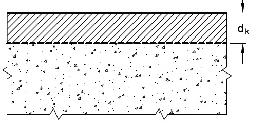
When the carbonation front runs as a straight line parallel to the surface, the depth of carbonation dk is determined as shown in Fig. 1A.
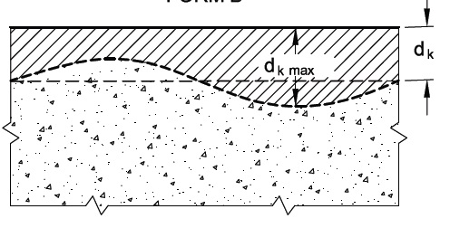
When the carbonation front runs as shown in Fig. 1B, a graphical average dk and the maximum depth dk max should be recorded.
Ignore greater depths of carbonation in the corner areas of laboratory specimens, where carbon dioxide has penetrated from two sides at once.
NOTES :
1 The measured depth of carbonation may be influenced by the time of measuring after application of the indicator solution. A stable reading may be obtained after about 5 to 10 min after spraying.
2 If only a weak colouration or none at all appears, it is better to repeat the spray after the surface has dried.
|
FORM A : 1A Straight Run Carbonation Front |
|
FORM B : 1B Varying Run Carbonation Front |
7. Corrections for Carbonation depth measurement
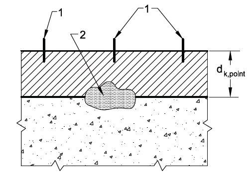
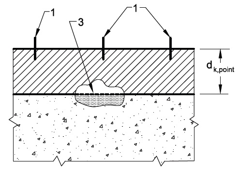
7.1. Procedure for Carbonation Depth Measurement when a Measurement Point Falls within a Dense Aggregate
-
Dense aggregate particles that lie within the carbonation
front will have no effect by the phenolphthalein solution
and the carbonation front will be interrupted by the
particle (see Fig. 2A). For determining the carbonation
depth, the theoretical carbonation depth at the plane of
intersection of the location point, a line connecting the
starting and ending point of the aggregate particle, shall
be used (see Fig. 2B).
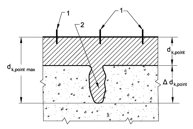
7.2 Procedure for Carbonation Depth Measurement when a Measurement Point Falls on an Air Void
-
When there are pores present in the area of the
carbonation front, extreme values of the carbonation
depth may appear (see Fig. 3). Where the measured
values of Δdk are less than 4 mm, they shall be used in
the calculation of the mean carbonation depth. Higher
values of Δdk shall not be included when calculating the
mean carbonation depth.
NOTE :Similar interference may also be observed in the case of porous aggregates.
|
2 A Dense Aggregate Interrupting Carbonation Front |
|
2 B Theoretical Carbonation Front Drawn Across Dense Aggregate |
|
Depiction of Carbonation Depth Where the Point Falls on an Air Void |
8. Test Results
-
The depth of carbonation for exposed face of a
specimen (dk,face) shall be calculated and recorded. A
minimum of three specimens shall be taken from each
structural member. The mean depth of carbonation for
each structural member (dk, spec) shall be calculated and
recorded.
8.1. Test Report
-
The test report shall contain the following:
a) Details of the concrete mixes/grade of concrete, if known;
b) Reference of the concrete under test such as location of member or any other identification code;
c) Age of structural member;
d) Date of test;
e) Mean carbonation depth of concrete in structural member;
f) Individual test results and average results with relevant photographic records including details on non-linear carbonation front and corrections due to dense aggregates/air voids; and
g) Any additional comments or observations.