Consolidation Test
1. objective
Consolidation test is used to determine the rate and magnitude of soil consolidation when the soil is restrained laterally and loaded axially. The Consolidation test is also referred to as Standard Oedometer test or One-dimensional compression test. This test is carried out on saturated soil specimens, especially in cohesive soils. The consolidation parameters obtained by this test are used to determine the consolidation settlement and time of consolidation for a given loading state (i.e. given height of embankment). These parameters are also used in design of “Ground Improvement measures”, provided for construction of embankment on soft soils.
2. apparatus required

|
| Fig. 1: Consolidation Test Apparatus |
2.1 Consolidation Ring
1. Shall be rigid and made of a non-corrosive material. The inner surface shall be smooth and highly polished, and coated with a low friction material.
2. It shall be provided with cutting edge to facilitate preparation of specimens.
3. The minimum inner dia shall be 60 mm. If soil specimens are to be obtained by the extruding and trimming, the inner dia of the ring shall be at least 10 mm less than the inside of the sampling tube.
4. Height of ring shall be minimum 20 mm, with diameter to height ratio of about 3.0. The specimen height shall not be less than 10 times the maximum particle size.
2.2 Porous Stones
1. They shall be of silicon carbide, aluminium oxide or other porous materials not attached by the soil.
2. Their porosity should be such that free drainage is assured during the test. If necessary, a filter paper may be placed between the stone and the soil surface.
3. The diameter of top stone shall be 0.2-0.5 mm less than the inside diameter of ring. The bottom stone shall be of large enough diameter to support the consolidation ring. The bottom stone shall be of large enough diameter to support the consolidation ring and the specimen adequately.
2.3 Consolidation Cell
The cell should be capable of being filled with water to a level higher than the top of the upper porous stone, of having an axial, vertical load applied to the top of the specimen and of allowing measurements of the change in height of the specimen on its central axis.
2.4 Dial Gauge
With accuracy of 0.01 percent of the specimen height and have a travel of at least 50 percent of specimen height.
2.5 Loading Device
1. Capable of applying vertical force to the test specimen and maintaining it for long periods of time.
2. It shall permit application of load increment within a period of 2 sec, without significant impact.
2.6 Jack and Frame:
For extruding the soil from sampling tubes.
2.7 Jig:
For holding the ring above the sampling tube.
2.8 Trimming Equipment:
Like metal straight edge, trimming knife, wire saw etc.
2.9 Equipment for measuring height of test specimen to an accuracy of 0.1 mm.
2.10 Equipment for determining moisture content of soil.
2.11 Balance sensitive to 0.01 Kg.
3. reference
IS 2720(Part 15):1986 Methods of test for soils: Determination of Consolidation Properties (First revision). Reaffirmed- Dec 2021.
4. procedure
- Weigh the empty consolidation ring, designated W1
-
If the specimen is to be prepared from a tube sample, a representative
sample for testing shall be extruded and cut off, care being taken to
ensure that the two plane faces of the resulting soil disc are parallel to each
other. The thickness of the disc of soil shall be somewhat greater than the
height of the consolidation ring.
If the specimen is to be prepared from a block sample, a disc similar in size to that specified above shall be cut from the block with two parallel faces. The diameter of the disc shall be at least 10 mm greater than the inside diameter of the consolidation ring. Care shall be taken to ensure that the soil stratum is oriented such that the laboratory test will load the soil in the same direction relative to the stratum as the applied force in the field. -
Using the weighed consolidation ring as a template, the edges of
the disc obtained in step 2 shall be trimmed carefully until the ring just
slides over the soil. The last fraction of soil is pared away by the cutting
edge of the ring as it is pushed down slowly and evenly over the sample
with no unnatural voids against the inner face of the ring; this process is
best done using a mechanical guide to prevent tilting or horizontal movement
of the ring. The top and bottom surfaces shall project above and
below the edges of the ring to enable final trimming.
Should an occasional small inclusion interfere with the trimming operation, it shall be removed, and the cavity filled completely with material from the parings. Alternatively, if sufficient sample is available, it would be preferable to eventually extrude and discard the portion of the specimen containing the inclusion from the ring, leaving a specimen free of such disturbed zones. If inclusions are known to exist in a soil sample, a large diameter consolidation ring should be used, in order to minimize the relative effect of the disturbed zones. If excessive inclusions are encountered during trimming, the sample should be discarded. If no alternative exists, the tube sample shall be extruded directly into a consolidation ring of equal diameter. - The soil sample thus obtained shall be trimmed flush with the top and bottom edges of the ring. For soft to medium soils, excess soil should be removed using a wire saw, and final trimming may be done with a straight edge if necessary. For stiff soils a straight edge alone may be used for trimming. Excessive remoulding of the soil surface by the straight edge should be avoided. In the case of very soft soils, special care should be taken so that the specimen may not fall out of, or slide inside the ring during trimming.
- A sample of soil similar to that in the ring, taken from the trimmings, shall be used for determining moisture content.
- The thickness of the specimen (H) shall be measured and it shall be weighed immediately (W2) should the nature of the soil make satisfactory thickness determination difficult, the ring height may be assumed as specimen height.
- The bottom porous stone shall be centered on the base of the consolidation cell. If soils sensitive to moisture increase (swelling or collapsing soils) are being tested, the stone should be placed dry. When testing softer clays, the stone should be wet, and it may be covered by a wet filter paper. No filter paper shall be used for the stiffer and moisture sensitive soils.
- The ring and specimen shall be placed centrally on the bottom porous stone, and the upper porous stone and then the loading cap shall be placed on top. The top stone shall be placed dry or wet, and with or without filter paper.
- The consolidometer shall be placed in position in the loading device and suitably adjusted. The dial gauge is then clamped into position for recording the relative movement between the base of the consolidation cell and the loading cap. A seating pressure of 0.05 kgf/cm2 shall be applied to the specimen.
- The consolidation cell shall be filled with water, preferably with distilled water. The type of water used shall be noted in the data sheet
- The specimen shall then be allowed to reach equilibrium for 24 hours.
- For consolidation testing, it is generally desirable that the applied pressure at any loading stage be double than that at the preceding stage. The test may, therefore, be continued using a loading sequence which would successively apply stress of 0.1,0.2,0.4,0.8, 1.6, 3.2, etc, kgf/cm2 on the soil specimen.
-
For each loading increment, after application of load, readings of
the dial gauge shall be taken using a time sequence such as 0, 0.25, 1, 2.25,
4,6.25,9, 12.25, 16, 20.25, 25, 36, 49, 64, 81, 100, 121,144, 169, 196, 225, etc, min, up to 24 hour(s) or 0,
1/4, 1/2, 1, 2, 4, 8, 15, 30, 60 min, and 2, 4, 8, 24 hour(s). These time sequences facilitate plotting of thickness or change of
thickness of specimen against square root of time or against logarithm of time
The loading Increment shall be left atleast until the slope of the characteristic linear secondary compression portion of the thickness/versus log time plot is apparent, or until the end of primary consolidation is indicated on a square root of time plot. A period of 24 hours will usually be sufficient, but longer times may be required. If a period of 24 hours is seen to be sufficient, it is recommended that this commonly used load period be used for all load increments. In every case, the same load increment duration shall be used for all load increments during a consolidation test. - It is desirable that the final pressure be of the order of at least four times the pre-consolidation pressure, and be greater than the maximum effective vertical pressure which will occur in situ due to the overburden and the proposed construction.
- On completion of the final loading stage, the specimen shall be unloaded by pressure decrements which decrease the load to one-fourth of the last load. Dial gauge readings may be taken as necessary during each stage of unloading. If desired, the time intervals used during the consolidation increments may be adopted; usually it is possible to proceed much more rapidly.
- In order to minimize swell during disassembly, the last unloading stage should be to 0.05 kgf/cm2 which should remain on the specimen for 24 hours. On completion of this decrement, the water shall be siphoned out of the cell and the consolidometer shall be rapidly dismantled after the release of the final load. The specimen, preferably within the ring, shall be wiped free of water, weighed (W3), and thereafter placed in the oven for drying. If the ring is required for further testing, the specimen may carefully be removed from the ring in order to prevent loss of soil, and then weighed and dried.
- Following drying, the specimen (plus ring) shall be reweighed (W4).
- The porous stones shall be boiled clean after the test, in order to prevent clay from drying on them and reducing their permeability.
-
Plot dial gauge readings versus square root of "t" (see Graph 1) for
each load increment and draw smooth curve joining the point. Each curve
should be identified by noting down the pressure acting on the specimen
during the load increment and the duration of the load increment. The
coefficient of consolidation, "Cv" determined from the curve, shall be
recorded on the curve as well.
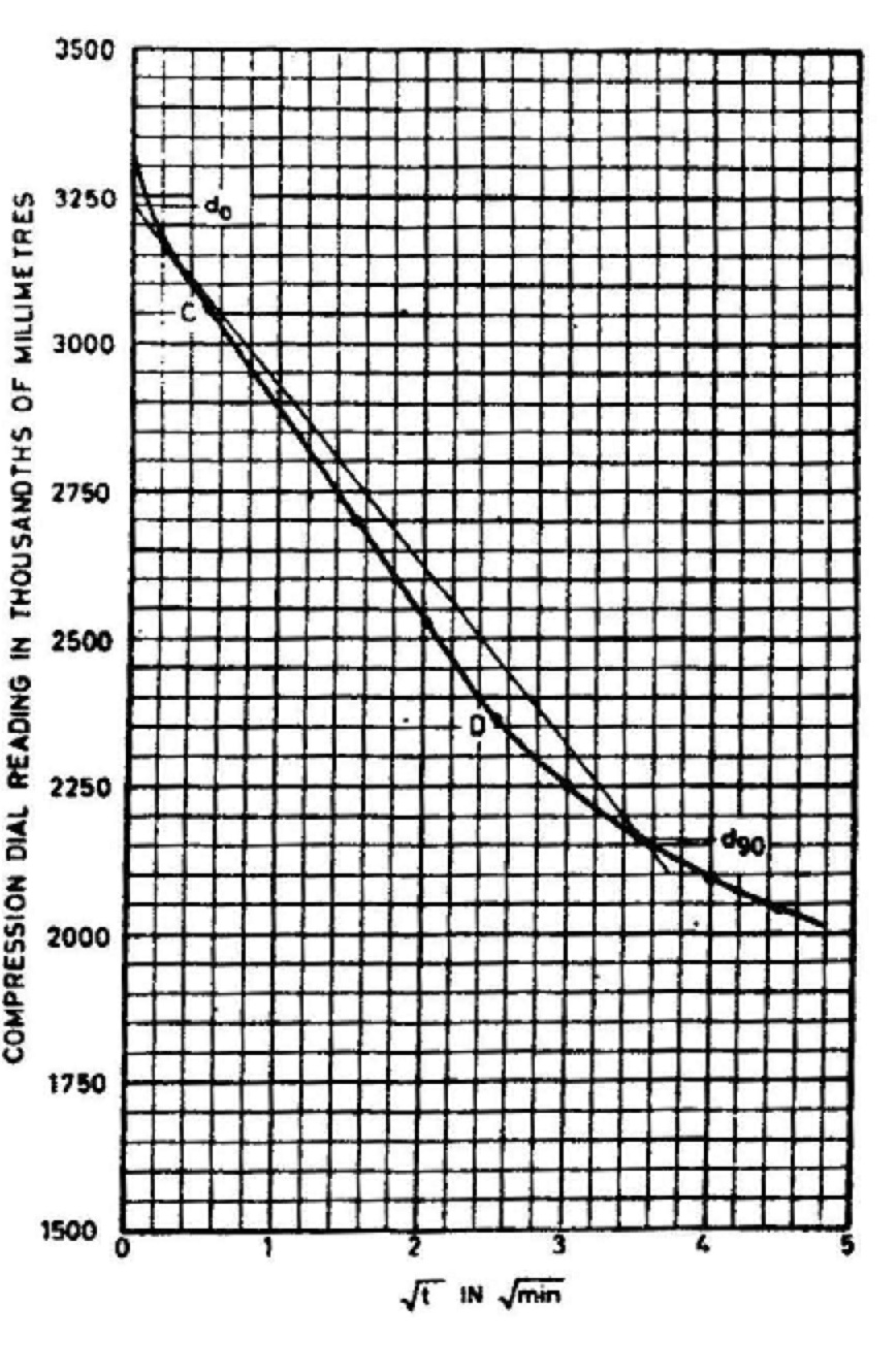
Graph 1:Plot of dial gauge readings versus square root of "t"
- The dial reading corresponding to zero primary consolidation, that is, do, is found by extrapolating the straight line portion of the curve, that is, DC back to t = O.
- Straight line is then drawn from do such that the abscissae of this line are 1.15 times the abscissae of the straight line CD.
- The point at which the drawn line intersects the experimentally obtained curve , that is, d90, corresponds to 90 percent primary consolidation
- The time required for 90 percent consolidation is read off the curve as t90 and recorded in col 9 of Appendix A.
-
The coefficient of consolidation, CV for the load increment
under consideration may be calculated from the formula below:
CV = {0.848 X (Hav/2)2}/t90
Where Hav is the average specimen thickness for the load increment given in col. 10 of Appendix A and CV has units of length2 per unit time consistent with the units used and should be recorded in col. 11 of Appendix A. - Transfer the final dial gauge reading for each pressure increment from Appendix-B to Col. 2 of Appendix-A, recording it against the total applied pressure which is noted in Col. 1 of Appendix-A.
-
From the dry weight of the specimen, Ws, the volume of soil
voids, Vs shall be obtained as:
Vs = Ws / Gs γw
Where:
Gs = specific gravity of the solid particles, and
γw = unit weight of water. - The equivalent height of soil solids can be determined as:
Hs = Vs / A
Where, A is area of specimen in cm2 - From Col. 2 of Appendix-A, determine ΔH for each pressure increment and record it in Col. 3.
- The height of specimen at the end of each pressure increment, H, can be determined by subtracting ΔH of a particular increment from H of the specimen prior to application of that increment. This is to be recorded in Col. 4 of Appendix-A.
-
Void ratio, e, is obtained as:
e = (H / Hs) - 1
and recorded in Col. 5 of Appendix-A. - Values of de and dσ obtained are recorded in Col. 6 and 7 of Appendix-A respectively.
-
The coefficient of compressibility, av, with units of inverse of units for stress shall be calculated as:
av = de / dσ
and recorded in Col. 8 of Appendix-A.
4.1 Preparation of Test Sample
4.2 Asembly of Apparatus
4.3 Loading
5. observation and recording
The specimen data shall be recorded at the top of the data sheet shown in Appendix A. This includes apart from soil identification, etc, specific gravity of soil particles, the specimen measurements and water content determinations. The specimen preparation procedure and the type of water used shall also be specified
Appendix A
| Applied Pressure (kgf/cm2) | Final Dial Reading | Compression ∆H (cm) | Specimen Height, HS (cm) | e = (H/HS)-1 | de | dσ | av = (de)/ (dσ) (cm2/kg) | t50 or t90 min | Hav | Cv (cm2/min) |
|---|---|---|---|---|---|---|---|---|---|---|
| 1 | 2 | 3 | 4 | 5 | 6 | 7 | 8 | 9 | 10 | 11 |
| a | ||||||||||
| b | ||||||||||
| c | ||||||||||
| d |
The data concerning dial readings with time for each pressure increment for both loading and unloading stages shall be recorded on the data sheet shown in Appendix B.
Appendix B
| Date and Time | Elapsed Time (minute) | Dial Reading | Date and Time | Elapsed Time (minute) | Dial Reading | Date and Time | Elapsed Time (minute) | Dial Reading | Date and Time | Elapsed Time (minute) | Dial Reading |
|---|---|---|---|---|---|---|---|---|---|---|---|
| 1 | 2 | 3 | 4 | 5 | 6 | 7 | 8 | 9 | 10 | 11 | 12 |
| a | |||||||||||
| b | |||||||||||
| c | |||||||||||
| d |
The data obtained after specimen disassembly concerning the final wet weight of the specimen (W3) and the dry weight (W4) shall be recorded in space provided in Appendix A.
6. calculation
6.1 Determination of Coefficient of Consolidation (Cv)
6.2 Determination of Coefficient of Compressibility av
6.3 Determination of Compression Index (Ce):
Plot the void ratio, e versus log σ. The slope of the straight line portion, that is, for the soil in the normally consolidated state, is designated as Ce. This can be directly obtained from the plot or calculated as
Ce = de /log (σ2/σ1)
Where: where σ2 and σ1 are the successive values.7. Presentation of Results
The results of a consolidation test are presented in the form of a set of curves showing the relationship of e versus and log σ, av versus log σ and Cv versus log σ. The value of Ce is also reported separately.